
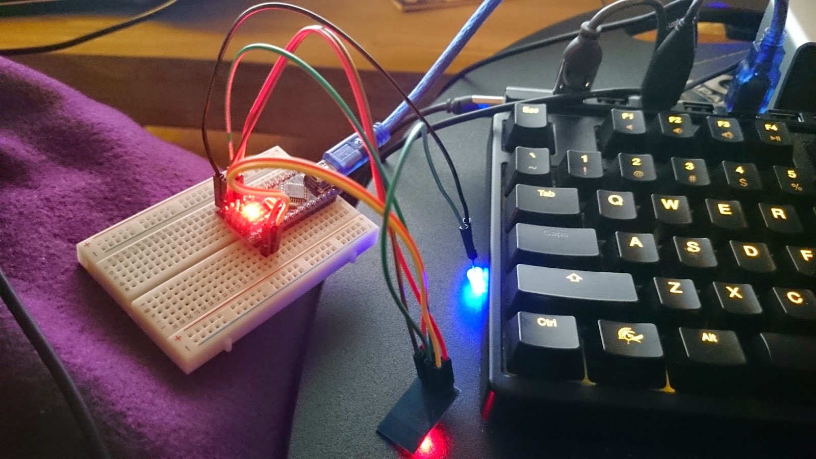
To get started with the ESP8266 ESP-01 I recommend flashing and programming it before soldering it down. This way you know it’s working and that the program code is also functioning. Depending on how you mount it on your board it can be a bit hard to do so later on!
This series has been rebooted
Please take a look at the following post to visit the new rebooted series and index of all posts: http://blog.quindorian.org/2016/07/esp8266-lighting-revisit-and-history-of-quinled.html/
Firmware flash mode
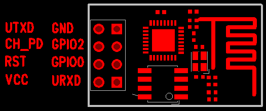
| Schematic overview of the ESP-01. Mind the orientation of the board, this is viewed from the top side |
Normal running mode
Since two pins need to be connected to 3.3v it’s easiest to either use a breadboard with some dupont cables or a screw connector block to multiply the connection.
Flash mode
To get into firmware flash mode you need to make two additional connections, easiest is to use a screw connector block or breadboard for this.
Downloading the software
You should end up with a zip file with all the files in it. Extract it. The files we are looking for are located in the nodemcu-firmware-masterpre_build.9.4512k-flash directory and the file we are going to flash is nodemcu_512k_latest.bin

Sadly, this isn’t as easy as it was written here, it should be, but the 3 modules I flashed needed toying and trying again and again for about an hour each to actually get it to go into flash mode. Once it did there was no problem and it flashed just fine, but still it was a bit hard to get it do so sometimes. I still don’t know yet why it doesn’t always work the first time, it might be because I was using a 5v Arduino.
Installing the QuinLED program on the ESP-01
- node.restart(); – Restarting the ESP8266
- wifi.setmode(wifi.STATION) – Setting it to WiFi client mode
- wifi.sta.config(“SSID”,”PASSSSS”) – Connecting to your WiFi network
- print(wifi.sta.getip()) – Get the IP of the ESP8266
- wifi.sta.connect() – Connect to the set SSID
- wifi.sta.disconnect() – Disconnect wireless
- print(“Hello World!”) – Print some text
pwm.setup(3, 1000, 005)
pwm.setup(4, 1000, 005)
pwm.start(3)
pwm.start(4)

LED1_current=005
LED1_target=005
LED2_current=005
LED2_target=005

Fadetime1=5000
Fadetime2=5000

Stepcounter1=0
PosStepcounter1=0
DimTimer1=0

Stepcounter2=0
PosStepcounter2=0
DimTimer2=0

wifi.setmode(wifi.STATION)
wifi.sta.config("SSID","PASSSS")


srv=net.createServer(net.TCP)
srv:listen(43333,function(conn)
    conn:on("receive",function(conn,payload)

    print("Input:"..payload)

    if string.find(payload,"LED1") then
     LED1_target=tonumber(string.sub(payload, 13) )
     print("Received LED1 Target Value: "..LED1_target)

     Stepcounter1=(LED1_target)-(LED1_current)

     if (Stepcounter1) < 0 then
      PosStepcounter1=(Stepcounter1)*-1
      else PosStepcounter1=(Stepcounter1)
     end

     if (PosStepcounter1) == 0 then
      PosStepcounter1=(PosStepcounter1)+1
      else PosStepcounter1=(PosStepcounter1)
     end

     DimTimer1=(Fadetime1)/(PosStepcounter1)

     if (DimTimer1) == 0 then
      DimTimer1=(DimTimer1)+1
      else DimTimer1=(DimTimer1)
     end

      print (Fadetime1)
      print (Stepcounter1)
      print (PosStepcounter1)
      print (DimTimer1)
      print (LED1_current)
      print (LED1_target)


    tmr.alarm(0, (DimTimer1), 1, function()
     if LED1_current < LED1_target then
      LED1_current = (LED1_current + 1)
      pwm.setduty(3, LED1_current)
    elseif LED1_current > LED1_target then
      LED1_current = (LED1_current - 1)
      pwm.setduty(3, LED1_current)
    elseif LED1_current == LED1_target then tmr.stop(0)
     end end )
    end

    if string.find(payload,"LED2") then
        print("Received LED2 Target Value")
     LED2_target=tonumber(string.sub(payload, 13) )

     Stepcounter2=(LED2_target)-(LED2_current)

     if (Stepcounter2) < 0 then
      PosStepcounter2=(Stepcounter2)*-1
      else PosStepcounter2=(Stepcounter2)
     end

     if (PosStepcounter2) == 0 then
      PosStepcounter2=(PosStepcounter2)+1
      else PosStepcounter2=(PosStepcounter2)
     end

     DimTimer2=(Fadetime2)/(PosStepcounter2)

     if (DimTimer2) == 0 then
      DimTimer2=(DimTimer2)+1
      else DimTimer2=(DimTimer2)
     end

      print (Fadetime2)
      print (Stepcounter2)
      print (PosStepcounter2)
      print (DimTimer2)
      print (LED2_current)
      print (LED2_target)


    tmr.alarm(1, (DimTimer2), 1, function()
     if LED2_current < LED2_target then
      LED2_current = (LED2_current + 1)
      pwm.setduty(4, LED2_current)
    elseif LED2_current > LED2_target then
      LED2_current = (LED2_current - 1)
      pwm.setduty(4, LED2_current)
    elseif LED2_current == LED2_target then tmr.stop(1)
     end end )
    end
    end)
    end)

print ("Booted to QuinLED_ESP8266_V0.4")
When you have it pasted in ESplorer press the “Save to ESP” button to transfer it over. It will ask you for a filename and where to store it. The where is only a local place what the file will also be kept, the filename is important and I recommend you name it “init.lua”. That way it will automatically run when the ESP-01 boots.
The tool should now be pasting the code to the ESP-01 line per line and checking if it made it across intact. I sometimes have that the code will arrive corrupt and the tool will error. When that happens I recommend you give the ESP-01 a restart and then a WiFi disconnect command. Doing that always makes the ESP-01 much more stable for me and transferring the program shouldn’t be a problem.
Once the ESP-01 is programmed it might complain that it can’t start a second TCP server (it depends on what you where running or if you had some fail flashes). Just give the unit a reset.
Once it’s booted again you can use the above mentioned commands to ask for it’s IP. You should be able to ping that IP. Don’t be alarmed by it’s ‘not so great’ ping times, this is normal.
Issuing commands to the ESP-01 running QuinLED
echo LED1_target=1000 | nc ip.ip.ip.ip 43333
That should said GPIO0 to a duty cycle of 1000. A duty cycle can be anything in the range of 0 to 1023. Do not use a number higher then that because right now the program will crash. 😉 It’s no use anyway because the ESP8266 supports 1024 PWM duty cycle levels so 1023 is fully open.

And that should be it, you can now control both channels of the ESP-01 connected to your LED strip. In my next post I will explain how you can hook this up into Domoticz and give it control over both channels independently.